| |
Heat Transfer
The key to understanding ampacity is to learn about heat transfer. The
definition of ampacity is given in the National Electrical Code (NEC) as
"the current in amperes a conductor can carry continuously under the conditions
of use without exceeding its temperature rating." To better understand
ampacity we need to examine how heat is transferred and thermal circuits
in respect to a current carrying conductor.
When current is carried by a conductor it must pass through the electrical
resistance of the conductor. When this happens heat is generated. One unit
of heat, watts, can be calculated by I squared times R, where R equals
the electrical resistance of the conductor in ohms and I equals the current
in amperes. The heat generated in the conductor passes through several
thermal barriers by convection, conduction, and radiation and dissipates
into the air. Possible thermal barriers are the conductor insulation, the
air inside a duct, the duct wall, the soil surrounding an underground duct,
and any additional thermal insulation applied such as polyurethane.
The transfer of heat follows a fundamental law in physics, and heat
always flows from the warmer object to the colder object, much like heat
flowing from the inside of a house through the walls to the outside on
a cold day. The rate of heat transfer is dependent on several variables
and can be described by a thermal equation that closely resembles ohms
law (E=IxR), substituting heat for current and thermal resistance for electrical
resistance. In a heat transfer equation the rate of heat transfer is directly
dependent on the difference in temperature between the conductor called
TC and the ambient temperature called TA. In a heat transfer equation TC-TA
= (IxIxR) x RCA, where I is current in amperes, R is electrical resistance
in ohms, and RCA is thermal resistance in degrees Centigrade-cm/watt usually
called thermal-ohm-feet. TC is the maximum permissible operating temperature
in degrees Centigrade of the conductor. TA is the ambient temperature of
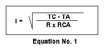
the air or soil for underground installations. Solving for I:
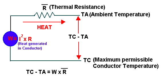
Letting heat, IxIxR in this case, be represented by W and thermal resistance,
RCA, by R with a line over it, we can draw a thermal circuit that is similar
to an electrical circuit.
Heat will flow from hot to cold objects until an equilibrium temperature is reached.
1. Temperature remains constant if heat loss = heat gain
2. Effectiveness depends on substances and situation
Neher-McGrath equation
Discovered by Joseph Fourier in the 1807, Equation No. 1 is sometimes
called the Fourier heat transfer equation. The equation in section 310-15( C)
of the NEC, as seen below, called the Neher-McGrath equation, is a more complex version
of the Fourier heat transfer equation. The Neher-McGrath equation was discovered
by two cable engineers in 1957. In the Neher-McGrath (NM) equation, Delta
TD, is a term added to the ambient temperature, TA, to compensate for heat
generated in the jacket and insulation for higher voltages. Delta TD is
called the dielectric loss temperature rise and is insignificant for voltages
below 2000. Another term in the NM equation, (1+YC), is a multiplier used
to convert direct current resistance (RDC) to alternating current resistance
or impedance. For wire sizes smaller than No. 2 this term becomes insignificant.
Of course, we must remember that the NM equation was developed using the
standard power frequency of 60 hertz and sinusoidal wave forms for current
and voltage.
There are many equations used to calculate the various thermal resistances
for the conductor insulation, the air space between a conductor and the
inside of a conduit, the conduit or duct wall, and the thermal resistance
outside the conduit. Like electrical resistors, thermal resistances in
series are added and the total equals RCA.
Ambient temperature, TA, varies but usually 30 or 40 degrees Centigrade
is used for above ground installations. For underground installations TA
is universally 20 degrees Centigrade. Civil engineers working for the State
of Alaska Department of Transportation state that the actual measured temperature
30 inches beneath the surface is 19.3 degrees Centigrade near Fairbanks,
Alaska. This of course, is during the summer months. The conductor temperature,
TC, for most 600 volt building wire is 60, 75, or 90 degrees Centigrade.
The maximum insulation temperature for conductors is determined by conducting
aging and enlongation tests in environmental chambers.
In the NM calculation there are many variables in the 30 to 40 equations
used to account for the number of conductors, number and size of adjacent
conduits, number and size of adjacent duct banks, coefficient of surface
emissivity, number of cables, axial spacing between cables, extraneous
heat sources, and wind velocity. All these factors and more effect the
calculation of ampacity. An analysis of the NM calculation reveals many
details about ampacity: for instance, the ampacity of conductors in a bright
and shiny conduit in free air is higher then the ampacity in a dull and
dark conduit because of the coefficient of surface emissivity and its effect
on the radiation of heat. Also, one of the most criticized faults of the
NM calculation is revealed: The calculation is based on one single linear
foot of a conductor that may be several hundred feet long where the conditions
vary dramatically along the entire length.
There are ampacity tables in the National Electrical Code that are sufficient
for most installations. However, the tables in the NEC are very crude approximations
and therefore include a substantial safety margin. There are instances
where the application of the ampacity tables including the safety margins
are insufficient requiring engineers, installers, and inspectors to perform
actual NM calculations using one of the several software packages available.
For instance, there are no requirements in the NEC to address the problem
of excessive thermal insulation around cables and conduits. What happens
if there are several inches of polyurethane foam around a conduit? There
are no derating tables in the NEC for this kind of situation. Yet, the
addition of excessive thermal insulation will effect the ampacity of a
conductor, especially polyurethane foam that has twice the insulation value
of fiberglass. To address this problem we must remember that the NM equation
is a radial heat transfer equation and that the NM calculation is performed
on one typical foot of an installation that may be several hundred feet
long. Radial heat transfer means that heat flows outward at ninety degrees
to the length of the conductor as opposed to axial heat transfer where
heat flows along the length of the conductor. In the real world there is
axial and radial heat transfer. But the NM equation and the NEC assume
that a conductor and surrounding thermal barriers are infinitely long and
uniform where no axial heat transfer takes place. There are, however, some
allowances in the NEC for axial heat transfer. For instance, there are
no derating for over three current carrying conductors in a nipple if the
nipple is not over 24 inches long. Also, bundled cables are not required
to be derated if the bundles are not longer than 24 inches. There is also
the ten per cent rule given in section 310-15(c). These are situations
where there is enough axial heat transfer to prevent the conductors from
overheating. It would also be prudent to assume that where there is excessive
thermal insulation not over 24 inches long, the ampacity of the applicable
conductors would not be effected because of axial heat transfer.
Derating for 600 volt 3-phase, 60 Hz for Excessive
Thermal Insulation using the R-value - Three Single Conductors in
a Raceway in free air.
Derating is required for excessive thermal insulation. This derating
can be done using the R Value for one inch of the insulation. R Values
are typically about 3.2 per inch for fiberglass and 6.0 per inch for sprayed
on polyurethane foam. Multiply the R Value for one inch
of insulation (that is in BTUth-in / hr-ft*ft-F) by 694 to convert
to C-cm / Watt, the units used in the Neher McGrath Equation for finding
thermal ohm feet. The equation using the R value is Ri = (.012)*694*R-Value*LOG10(Outside
Diameter of thermal insulation in inches/Outside Diameter of Raceway in
inches)
For a quick approximation of the derated ampacity add this calculated
thermal ohm feet value to the RCA value used in the NM original calculation
and recalculate the ampacity. Finding the original RCA value is easier
than it looks. Use the ampacity from Table in 310.15(B)(16) in the 75 degree
column. Use TA = 30, TC = 75, degrees C. Next find the 75 degree
C. DC resistance from Table 8 in Chapter 9. Multiply this resistance
by 1000 to convert to microhms per foot of conductor, the value and
units used in the NM equation. Use this for RDC in the NM equation.
Now solve the NM Equation 1, above, to find RCA. Next recalculate
ampacity using the NM equation, but this time add the new Ri value for
the thermal insulation to RCA found using the original data. The
new ampacity is your derated ampacity. This method can be used for other
temperature ampacities if the resistance from Table 8 Chapter 9 is recalculated
for the same temperature as the conductor ampacity temperature.
This procedure is a quick approximation and assumes no axial heat transfer
and uses DC resistance for impedance that may vary for wire sizes above
No. 2 depending on power factor. Remember the NM equation gives ampacity
in kiloamperes so you have to multiply by 1000 to get amperes. Also,
the thermal insulation is assumed to be evenly spaced around the raceway
or cable.
This method does not apply if there are different types of thermal
insulations along the length of the raceway or cable such as where the
raceway or cable may pass through wooden members. In these cases
boundary limits can be found by assuming that the intervening thermal
medium with the lower R-value is the primary thermal insulation.
Wood has an R-value of .89 for hardwoods to 1.48 for cedar. These
lower R-values can set a limit on the maximum ampacity while the higher
R-values can establish the minimum ampacity. A more advanced
method using the calculus of finite differences can be used if more accurate
results are required. This is a subject covered in heat transfer
physics taught in mechanical engineering. R-values and thermal conductivity
values can be found in the 1985 ASHRAE Handbook.
Derating for 600 volt 3-phase, 60 Hz for Excessive
Thermal Insulation using the N-M Equation - Three Single Conductors
in a Raceway in free air.
The chart below was made using the values found with an Excel 7.0
spread sheet calculator. In this calculation the R values were not
used although the calculator has two methods, one using the thermal conductivity
and one using the R-Values. The thermal conductivity values
in BTU-in/hr-ft*ft-F were used to calculate the chart. These values
were multiplied by .00144131 to convert them to W/cm C and then the
inverse of W/cm C was taken to get the correct units, C-cm/Watt,
of Thermal resistance for the Neher McGrath calculation. These values
were confirmed by using a United Kingdom internet web page calculator at http://www.omnis.demon.co.uk/
to verify that no errors had been made. The normal ampacity was calculated
using the N-M equation following the format given in IEEE paper "Neher McGrath
Calculations for Power Cables" by Peter Pollack written in 1984. This
method, shown below in the example, gives good results for under 2,000
volts and for building wire applications leaving out some of the more
complicated equations in the N-M paper.
The second part of the spread sheet calculation found the thermal
resistance of the insulation for sprayed on polyurethane foam and loose
cellulose and fiberglass using the same equation that was used to calculate
Ri.. The Re value is subtracted from the first RCA value then the
thermal resistance, Ri''' of the thermal insulation is added to the initial
Ri and Rsd values. A new Re is calculated for the thermal insulation
using an emissivity of .3 since the insulation is assumed to not be bright
and shiny. This new Re’’’ value is added to the Ri, Rsd and Ri’’’
to find the new RCA value. This value of RCA is then used to perform
a new N-M calculation to find the ampacity. The new ampacity is divided
by the previously calculated ampacity and multiplied by 100 to give per
cent derating. The per cent derating then when multiplied times the
first ampacity calculated gives the reduced ampacity found in the second
calculation. The advantage of the spread sheet is that the
many variables can be changed and the new values are instantaneously calculated.
Cells with formulas in the spread sheet have been locked so the spread
sheet must be unprotected to change them. The accuracy of this calculator
can be checked by comparing calculated values to the values in Table
310.15(B)(16)
and by comparing the calculated ambient derating factors to the ambient
derating factors at the bottom of Table 310.15(B)(16).
The AC resistance of a single foot of conductor effects the N-M Calculation
significantly. For wire sizes above No. 2 Table 9 in Chapter 9 of
the NEC should be used to find the AC impedance instead of using the DC
resistance, either calculated or taken from table 8 in Chapter 9.
The spreadsheet calculator calculates AC resistance in the same manner
as the Pollack paper. First the DC resistance is calculated using
the N-M paper formula for the temperature TC, using 12.9 ohms, the circular
mil ohms per foot at 75 degrees C. for copper. The DC resistance
is multiplied by the AC/DC ratio. The AC/DC ratio is taken from
the Standard Handbook for Electrical Engineers Tenth Edition Page 17-20.
To use the
spreadsheet Calculator for Excel 7.0 click here.
The below graph is from the spreadsheet. The 3/0 are 3 each THWN
copper in 1 1/2 inch EMT and the No. 2 copper are 3 XHHW each in a 1 inch
rigid in free air . Poly is for sprayed on polyurethane foam and
the cell is for fiberglass or cellulose. An ambient of 30 degrees C is
used. Tc is 90 degrees C for the No. 2 and 75 degrees C for the 3/0.
A thermal conductivity of .17 BTU-in/hr-ft*ft-F is used for polyurethane
and .30 BTU-in/hr-ft*ft-F is used for fiberglass or cellulose.

Neher McGrath Table VII
Constants used for finding Rsd
| Condition |
A
|
B
|
C
|
A'
|
B'
|
| In metallic conduit |
17
|
3.6
|
0.029
|
3.2
|
0.19
|
| In fiber duct in air |
17
|
2.1
|
0.016
|
5.6
|
0.33
|
| In fiber duct in concrete |
17
|
2.3
|
0.024
|
4.6
|
0.27
|
| In transite duct in air |
17
|
3.0
|
0.014
|
4.4
|
0.26
|
| In transite duct in coincrete |
17
|
2.9
|
0.029
|
3.7
|
0.22
|
| Gas-filled pipe at 200 psi |
3.1
|
1.16
|
0.0053
|
2.1
|
0.68
|
| Oil filled pipe or duct |
0.84
|
0
|
0.0065
|
2.1
|
2.45
|
Ds' = multiplier for converting circumscribed conductors to equivalent
circle.
| 1.00 x diameter for one cable |
| 1.65 x diameter for two cables |
| 2.15 x diameter for three cables |
| 2.50 x diameter for four cables |
Decimal Equivalents
|
1/16
|
.0625
|
|
1/8
|
.125
|
|
3/16
|
.187
|
|
1/4
|
.250
|
|
5/16
|
.312
|
|
3/8
|
.375
|
|
7/16
|
.437
|
|
1/2
|
.500
|
|
9/16
|
.562
|
|
5/8
|
.625
|
Dimensions of EMT
Electrical Metallic Tubing
Trade Size in Inches
|
Outside Dia. in Inches
|
Inside Dia. in Inches
|
Wall Thickness in Inches
|
|
1/2
|
.706
|
.622
|
.042
|
|
3/4
|
.922
|
.824
|
.049
|
|
1
|
1.163
|
1.049
|
.057
|
|
1 1/4
|
1.510
|
1.380
|
.065
|
|
1 1/2
|
1.740
|
1.610
|
.065
|
|
2
|
2.197
|
2.067
|
.065
|
|
2 1/2
|
2.875
|
2.731
|
.072
|
|
3
|
3.500
|
3.356
|
.072
|
|
3 1/2
|
4.00
|
3.834
|
.083
|
|
4
|
4.500
|
4.334
|
.083
|
|
5
|
--
|
--
|
--
|
|
6
|
|
|
|
Dimensions of Rigid Conduit
Steel or Aluminum
Trade Size in inches
|
Outside Dia. in Inches
|
Inside Dia in Inches
|
Wall thickness in Inches
|
|
1/2
|
.840
|
.632
|
.104
|
|
3/4
|
1.050
|
.836
|
.107
|
|
1
|
1.315
|
1.060
|
.126
|
|
1 1/4
|
1.660
|
1.394
|
.133
|
|
1 1/2
|
1.900
|
1.624
|
.138
|
|
2
|
2.375
|
2.083
|
.146
|
|
2 1/2
|
2.875
|
2.489
|
.193
|
|
3
|
3.500
|
3.090
|
.205
|
|
3 1/2
|
4.00
|
3.570
|
.215
|
|
4
|
4.500
|
4.050
|
.225
|
|
5
|
5.563
|
5.073
|
.245
|
|
6
|
|
|
|
Dimensions of IMC
Intermediate Metal Conduit
Trade Size in Inches
|
Outside Dia. in Inches
|
Inside Dia. in Inches
|
Wall Thickness in Inches
|
|
1/2
|
.815
|
.675
|
.070
|
|
3/4
|
1.029
|
.879
|
.075
|
|
1
|
1.290
|
1.120
|
.085
|
|
1 1/4
|
1.638
|
1.468
|
.085
|
|
1 1/2
|
1.883
|
1.703
|
.090
|
|
2
|
2.360
|
2.170
|
.095
|
|
2 1/2
|
2.857
|
2.597
|
.130
|
|
3
|
3.476
|
3.216
|
.130
|
|
3 1/2
|
3.971
|
3.711
|
.130
|
|
4
|
4.466
|
4.206
|
.130
|
|
5
|
--
|
--
|
--
|
|
6
|
|
|
|


|


